


Two electric trikes can be built from near-identical parts lists — same motor rating, same battery capacity, same sensor type — and ride so differently that a dealer would not stock one of them. The difference is not in the components. It is in how the components were configured to work together, and on a semi-recumbent trike built for older riders, that configuration decides whether the vehicle is usable by the people it was designed for at all.
This is the part of a drive system that no specification sheet describes. Below is what actually determines how a trike delivers assistance, the three points where we change it, and what a partner needs to tell us in order for us to get it right for their market.
Why a semi-recumbent trike is a different problem from an e-bike or a cargo bike
Most published thinking about e-bike drive systems assumes a rider who can stand on the pedals. On a semi-recumbent trike, almost none of that assumption holds, and the consequences run straight into how the drive system has to be set up.
The rider is seated and reclined, with their back supported and their legs working forward rather than downward. They cannot stand, cannot shift weight over the cranks, and cannot use body mass to break away from a standstill. Peak pedal force available to them is a fraction of what an upright cyclist can generate, and for the rider profile these trikes are built for it is lower again. A drive system calibrated around the pedal forces a fit cyclist produces will simply under-assist this rider at exactly the moment they need help.
Three wheels change the rest. A bicycle is self-correcting: the rider leans, and small errors are absorbed by balance without conscious effort. A trike does not lean, so cornering loads pass through the tyres and frame instead, and low-speed steering inputs are not automatically damped. A sudden arrival of torque is therefore not felt as acceleration but as the vehicle moving independently of the rider — which is why the first few metres from rest matter more here than peak power ever will.
The vehicle is also heavier, and it is operated stationary more often. Mounting, dismounting and loading all happen with the trike standing still, frequently on a slope. That places real weight on features which look like footnotes on a specification sheet: a parking brake that holds during mounting, internal gearing that can be shifted while stopped so a rider never has to set off in the wrong gear, a reverse assist for manoeuvring in a space too tight to turn.
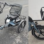
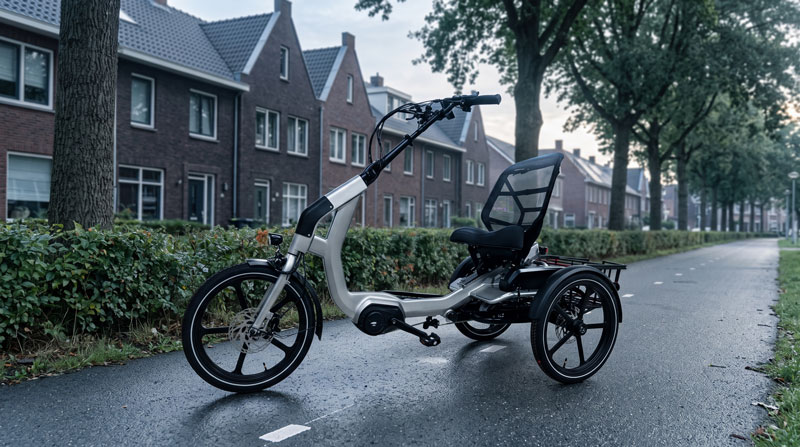
The CHILL is dimensioned around those facts rather than adapted to them — a 380 mm step-through, a seat height adjustable between 580 and 707 mm, 22° of backrest adjustment, a 1.6 m turning radius, a rear differential so the two driven wheels can turn at different speeds through a corner, and an internal 8-speed hub that shifts at rest. Those numbers describe the geometry. What the drive-system calibration has to do is make the vehicle behave consistently with them.
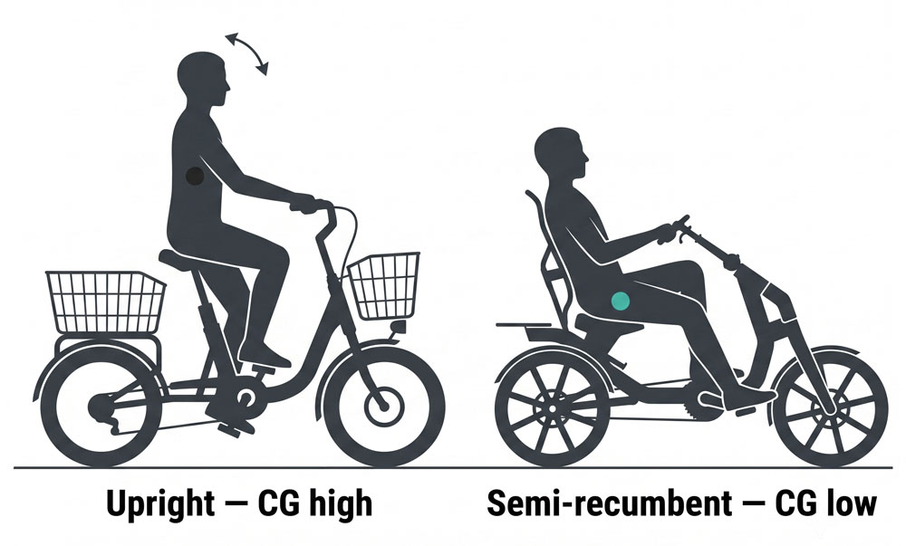
For contrast: on a cargo bike, calibration is dominated by payload — the same trike-like mass problem, but with a rider who can stand and compensate. On a conventional e-bike, the vehicle is light enough that a rider absorbs a poorly matched assist curve without really noticing. The semi-recumbent trike is the case where calibration has the least margin for error.
What actually determines motor output
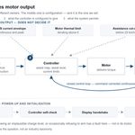
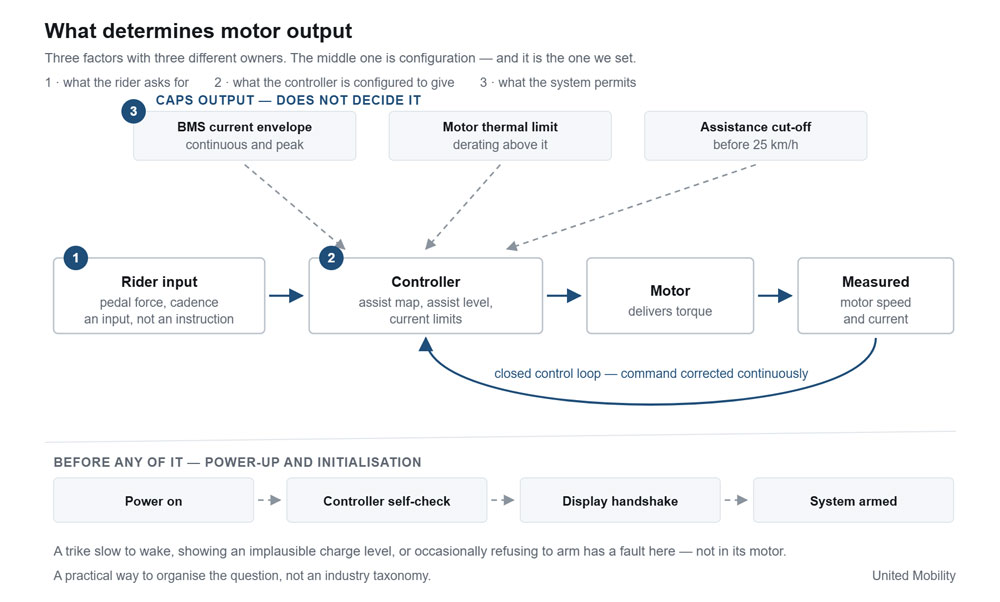
It is common to describe a drive system as a chain: you pedal, the sensor reads it, the controller acts, the motor turns. That is the signal path, and it is one-directional. It is not, on its own, an explanation of behaviour. Three things determine what the motor actually does at any moment.
What the rider asks for. The torque sensor reports pedal force. Cadence and wheel speed are reported alongside it. Together these are an input, not an instruction.
What the controller is configured to give. The controller interprets that input against an assist map, the selected assist level, vehicle speed and its own current limits, and commands a current to the motor. Motor speed and current are fed back and the command is corrected continuously — this part is a genuine closed control loop, and in most systems a nested one, with a fast inner current loop sitting inside a slower torque or speed loop. The shape of the map and the behaviour of that loop are configuration, not hardware.
What the system is permitted to deliver. Above the control loop sits a hierarchy of ceilings: the current envelope the battery management system allows, the motor’s thermal limit, and the legal assistance cut-off. None of these decide the output. They cap it.
Before any of that, the system has to start. Pressing the power button supplies the controller, which runs its self-check and establishes communication with the display before the system arms itself and reports charge level and mode. On a CAN-based system this exchange is a genuine bus handshake between nodes. It is worth knowing about for one practical reason: a trike that is slow to wake, shows an implausible charge level, or occasionally refuses to arm has a fault in initialisation or communication, not in its motor — and that is a materially cheaper diagnosis for a service network to reach.
This framing is not an industry taxonomy. It is the useful way to organise the question, because each of the three has a different owner: the first is the rider, the third is largely fixed by the components and the law, and the second — the middle one — is ours. Everything below is the middle one.
Calibration point one: the assist map
A torque sensor measures pedal force and nothing else. What the controller does with that measurement is the first and most visible configuration decision, and the same sensor supports maps with completely different characters.
Two maps from the same sensor
A speed-referenced map treats each assist level as a target speed. Light pedalling is enough to reach it, so output is high relative to rider input at the bottom of the range and then holds. A rider with limited leg strength keeps the motion and rhythm of cycling without needing the strength to generate it.
A force-proportional map makes output track pedal force across the whole range. Pedal harder and more arrives; ease off and it recedes. The rider stays in control of how much work they are doing, and the trike amplifies effort rather than replacing it.
Both can be made selectable from the display on the same vehicle. What they are called on screen is a project decision — partners selling under their own brand generally name them to suit their own market rather than inheriting ours.
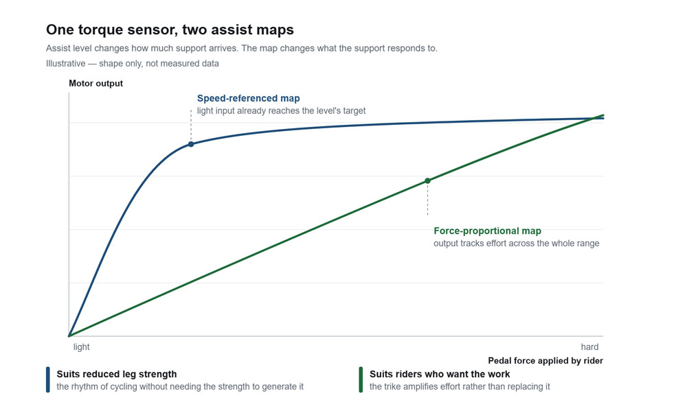
One distinction is worth drawing because specification sheets routinely blur it. Assist level changes how much support arrives. The map changes what the support responds to. The two are independent: a rider on a speed-referenced map at level 5 and a force-proportional map at level 1 is experiencing two things that have almost nothing in common, and a dealer demonstrating only one of them is showing half the product.
Neither map changes the vehicle’s legal character. In both, the motor delivers nothing when the rider stops pedalling, and assistance is progressively reduced and cut off before 25 km/h — the conditions under which a pedal-assisted cycle stays outside type-approval as an EPAC under Regulation (EU) 168/2013. Neither is a throttle. Neither should be confused with the start-up or walk-assist function that the harmonised EPAC standard permits up to 6 km/h without pedalling, which is a deliberately limited feature for moving the trike rather than riding it.
What that is worth commercially
The engineering here is not exotic. Torque sensing is widely available, and configurable assist maps are a controller capability rather than an invention. What is worth something is the specific pairing of two maps with the rider population a semi-recumbent trike actually sells to.
Households in this segment frequently contain two riders with materially different physical capacity — a pattern familiar to anyone selling into senior mobility or care channels, where a trike is bought by or for a couple. A single vehicle that covers both cases removes the need to stock or demonstrate two configurations for one household, and it widens what a single demonstrator on a showroom floor can be shown to do.
It also changes the return conversation. A trike that is too eager for one rider and too passive for the other tends to come back. One that can be set either way, in the shop, at handover, does not.
Calibration point two: the approach to the assisted speed limit
A frequent complaint on electric trikes is a surging or pulsing sensation as the vehicle approaches the top of its assisted range. It is a calibration artefact, not a fault.
Assistance has to be reduced progressively and cut off before 25 km/h; that is the requirement, and any compliant product does it. What differs is where the reduction begins and how it is shaped. Where the taper is narrow and steep, and where the controller has little or no hysteresis around the threshold, the system approximates a switch: output falls away, the trike decelerates, it re-enters the assisted range, output returns, and the cycle repeats. The rider feels a repeating surge and drop. On a loaded trike, with a reclined rider who cannot absorb it through their arms and legs, it is pronounced enough to be a reason not to buy.
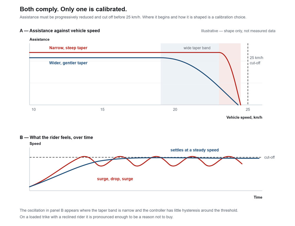
The fix is a wider taper band with a gentler slope and deliberate hysteresis, so the system passes through a transition rather than oscillating at a boundary. The controller and the display move together through that band and the trike settles at a steady speed instead of hunting around one. Neither configuration is more compliant than the other. One is simply calibrated and the other is merely legal.
The same body of work covers where the motor spends its operating time. Every motor has an efficiency band — a region of speed and load in which it converts current into torque most effectively and generates the least waste heat. Outside that band, the same current buys less useful output and more temperature rise, and sustained operation there eventually triggers thermal derating, at which point the controller reduces output to protect the motor and the rider experiences a trike that loses assistance halfway up a long climb. Matching the controller’s current limits and response shape to a particular motor’s efficiency band is what makes output steady across a full ride rather than strong for the first kilometre.
Three implications for anyone specifying a build. It is motor-specific, so it is redone whenever the motor changes. It cannot be read off a specification sheet, because a rated power figure says nothing about the shape of delivery. And it is precisely where two trikes with the same parts list end up feeling like different products.
Calibration point three: matching the controller to what the pack allows
The battery management system is usually described as a safety device. That is accurate but incomplete, and it is often stated in a way that overclaims what a BMS does.
A BMS defines an envelope. It sets the continuous and peak discharge current the pack will permit, monitors individual cell voltages and temperatures, keeps cells balanced so the pack ages evenly rather than being limited by its weakest cell, and intervenes — by limiting current or by opening the circuit — when a boundary is reached. Within that envelope it does not determine output. The controller does, according to the assist map and the rider’s input. The BMS sets the ceiling; the controller operates under it.
That distinction has a practical consequence, which is the most common avoidable failure in a configured build. If the controller’s peak demand exceeds what the BMS will continuously allow, the system will cut out under sustained load. The triggering conditions are exactly the ones that matter on a trike: pulling away fully loaded, or holding output through a long gradient. A build can pass every bench check and still shut down on a real hill, because those two numbers were never compared to each other.
The same arithmetic governs pairing a compact battery with a powerful motor. It is a legitimate choice, and there are good reasons to want it — weight, cost, packaging, or a market where range expectations are modest. What makes it work is setting the controller limits to what the pack will actually deliver rather than to what the motor could theoretically produce. The honest trade-off is that peak performance is then defined by the pack, not the motor. A smaller pack with correctly matched limits is sound engineering. A smaller pack behind a controller configured for a larger one is a warranty claim waiting for a gradient.
Hardware BMS or software BMS
The choice affects what a service network can see and what a compliance team will need.
A hardware BMS provides analogue protection — over-voltage, under-voltage, over-current, short circuit — with no communication path. State of charge is inferred from voltage, which sags under load, so the display reads low on a climb and recovers afterwards. Its current limit is a fixed trip point: when a boundary is crossed, it acts, and the rider gets a shutdown with no explanation. It is robust, inexpensive and opaque.
A software BMS runs a microcontroller, counts charge in and out, and reports over a communication protocol. State of charge is measurably more accurate because it is calculated rather than estimated. Fault conditions arrive at the display as identifiable codes instead of an unexplained cut-out. And because it can communicate, the permitted discharge current can be handed to the controller as a value that moves with cell temperature and state of charge, rather than sitting as a single hard limit — which means the drive system degrades gracefully at the edges instead of tripping.
That reporting capability is becoming a procurement question rather than a technical preference. Regulation (EU) 2023/1542 introduces battery passport obligations for light means of transport batteries from February 2027, and the data a passport expects — cycle history, state of health, pack identity — is data a software BMS already maintains and a hardware BMS does not. Any programme expecting to still be selling into the EU in 2027 should be specifying on that basis now. The sourcing and lifecycle side of this is covered separately in our battery strategy guide.
What validation covers
Calibration that has not been validated is an opinion. Part of the answer is defined externally, which is useful because it gives an objective floor rather than an internal one.
In Europe, type testing to the harmonised EPAC standard verifies that maximum continuous rated power is measured and documented rather than asserted, that assistance is progressively reduced and cut off before 25 km/h rather than switched, that start-up assistance without pedalling is limited to 6 km/h, that the motor cannot start unintentionally, and that the electrical circuit, wiring, protection and temperature rise behave correctly under load. Battery packs are covered separately, with pack safety to EN 50604-1 and transport testing to UN 38.3. For programmes entering North America, UL 2849 takes a notably similar view to ours: it evaluates the drive train, battery and charger as an integrated system rather than certifying components in isolation.
Above that floor sit the checks no standard describes, because they concern how the trike behaves rather than whether it is safe. How it sets off from rest fully loaded. Whether assistance holds through a sustained climb or derates early. How the transition through the taper band feels, rather than simply where it occurs. Whether displayed charge tracks reality under load. And what happens at the boundaries — full load, low charge, cold weather.
Both have to be true before a sample is approved. The standard establishes that a trike is safe and legal. It does not establish that anyone will want to ride it. The configuration and the evidence behind it then form part of the technical file supporting the Declaration of Conformity.
Not everything is solved by calibration, and it is worth saying so. Where a compact pack limits peak output, calibration manages the limit rather than removing it. Where a motor sits at the edge of its efficiency band for the terrain in a given market, the answer is a different motor, not a different curve. Part of the work is telling a partner when the specification they have asked for will not do what they want it to do.
What this means when you specify a build
Because all three calibration points are combination-specific, we do not publish a single gradeability figure or response time for a configurable platform. Any number published would be true of one configuration and misleading for every other. We calculate the figures for a specific configuration during quotation instead.
What we need in order to do that is narrower than it sounds: the terrain profile of the target market, the rider profile being sold to, the load the vehicle is expected to carry, and the target price position. Those four inputs determine the motor, the pack size, the controller limits and the assist maps. Everything after that is our work, and how a configured build runs from brief to series production sets out the stages it passes through.
Frequently asked questions
Is the assist map selectable by the rider, or fixed at the factory?
It is selectable from the display. That is the point of offering two maps on one vehicle rather than two vehicles. Where an application needs predictable behaviour across many different users — rental fleets, shared schemes, care institutions — fixing the configuration is worth raising at brief stage, because it is a specification decision rather than something to change later.
Does switching between maps affect EPAC status?
No. Both are pedal-assist: the motor delivers nothing when the rider stops pedalling, and assistance is progressively reduced and cut off before 25 km/h in either case. Neither drives the trike without pedal input, which is the distinction that keeps a pedal cycle outside type-approval under Regulation (EU) 168/2013.
Can we use a smaller battery to reduce cost?
Usually yes, provided the controller limits are set to what the pack will actually deliver. The binding constraint is the BMS continuous discharge rating against the controller’s peak demand, not the pack’s energy capacity. We will tell you what peak performance the smaller pack costs you before you commit to it. Capacities currently available on each platform are listed in the configuration options on the CHILL and Vita product pages.
If we change the motor later, does the calibration carry over?
No. Current limits, response shape and the taper band are matched to a specific motor’s characteristics, so a motor change means the calibration is redone and the combination revalidated. It is the main reason drive-system changes carry longer lead times than cosmetic ones.
How much time does calibration and validation add to a project?
It runs in parallel with the rest of development rather than sequentially after it, so in most cases it does not extend the critical path. Where a component we have not previously validated is introduced, it can — and we say so at quotation rather than at sample stage.
Which standards apply to a three-wheeled EPAC?
Certification scope is confirmed per project rather than assumed, because the harmonised standard for EPACs is written around two-wheeled bicycles and a three-wheeler is not automatically inside its stated scope. We agree the applicable standards and testing route with the partner and the notified body at the start of a project, which matters because under EU law the party placing the product on the market under its own brand is the manufacturer and holds the Declaration of Conformity. Our role is to supply the technical file and the test evidence that supports it.
What documentation do we receive?
The configuration record and the test evidence for that configuration, as part of the technical file supporting the Declaration of Conformity.
Related
- CHILL semi-recumbent electric trike — specification and configuration options
- Vita semi-recumbent electric trike — the compact platform
- Electric trikes for the elderly — fit, access and stability
- ODM and private-label manufacturing — how a configured build runs
- EU compliance guide — standards, CE marking and the technical file
 English
  German
  Dutch
Dutch  Danish
  French
  Polish
  Portuguese
  Spanish